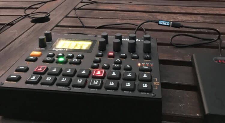
Elektron is a Swedish brand of very popular electronic musical instruments. Most of their devices run on 12-Volt DC and they come with a power supply unit (PSU-3) that is connected to a socket. Wouldn’t it be great to play your favorite Elektron device wherever you like without the need for a socket and is this even possible?
The short answer is yes, you can power your Elektron device grid independently. The most practical and affordable way is to use portable PD chargers (also called USB-C PD power banks or USB-C PD portable batteries). PD stands for “Power Delivery” and it’s a new fast-charging standard for smartphones and laptops. But how can you utilize these powerful batteries to power your Elektron device?
How to power Elektron devices from portable USB-C PD power banks?
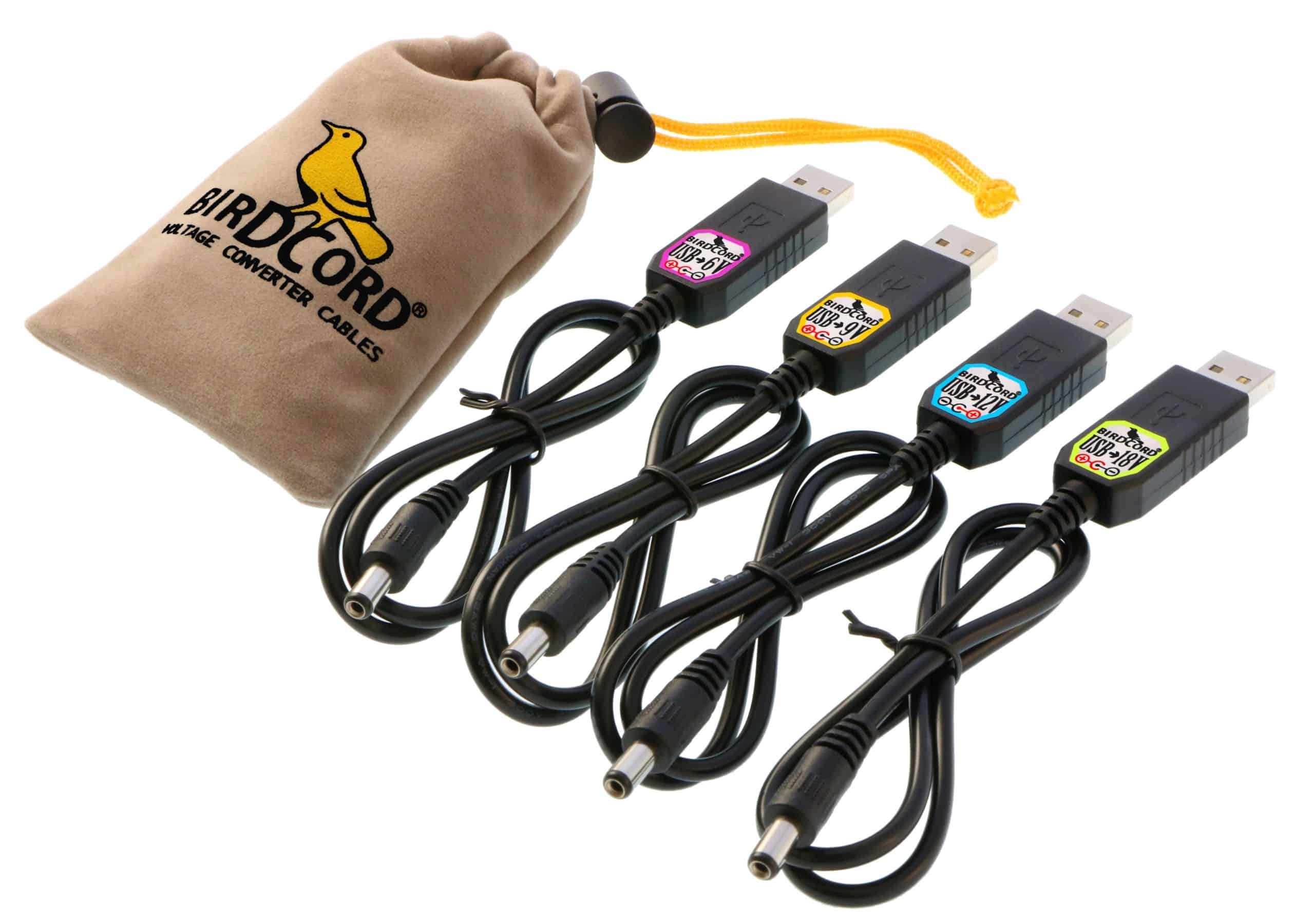
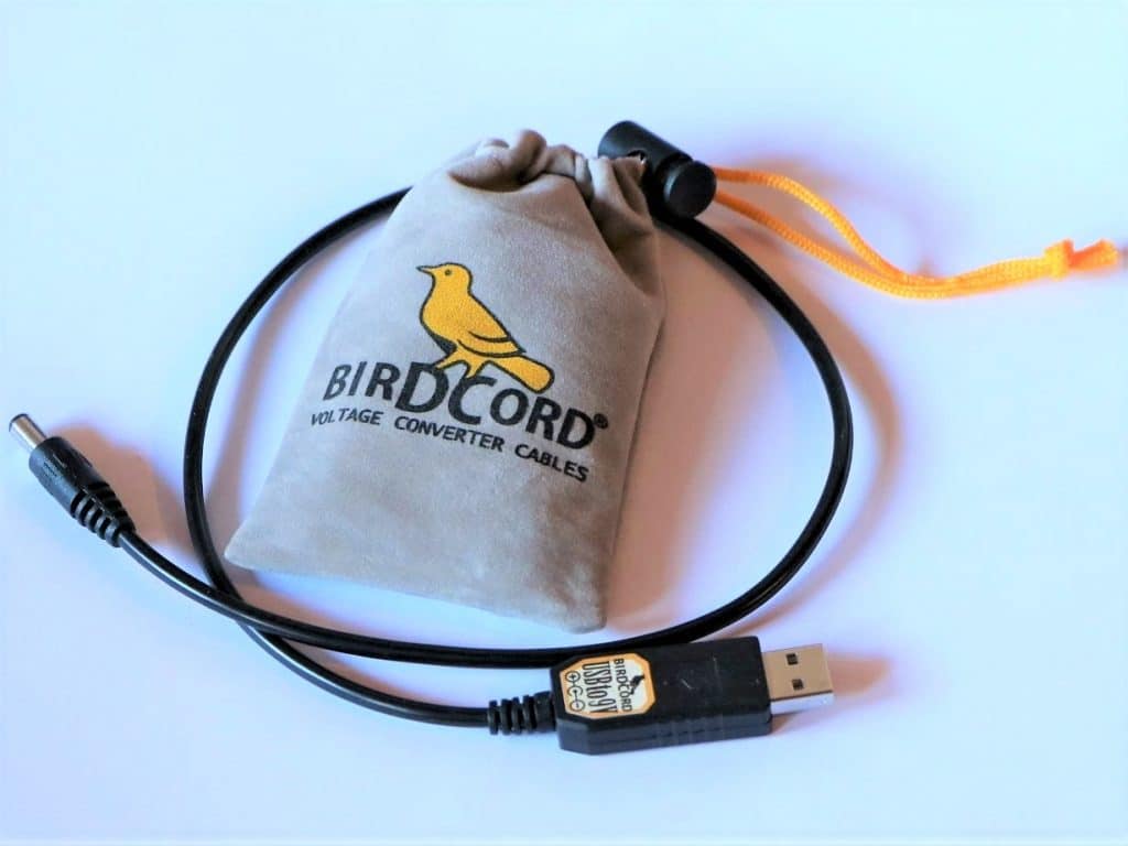
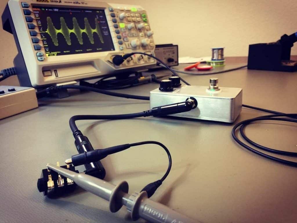
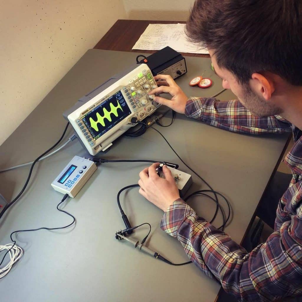
This is where our new product comes into play: The Birdcord PD 12V power cable allows you to connect a USB-C PD power bank to your Elektron device and it also tells the power bank to switch to 12V. This method gives you 36 Watts of power (3A@12V) so you can easily power any 12V Elektron device.
What do you need to make it work?
- a Birdcord PD 12V
- a USB-C PD power bank that is capable of 12V. Best choice: INIU 65W 20000mAh PD
- a USB-C cable to connect the power bank to the Birdcord
- your 12V Elektron device (of course)
What about non-12V Elektron models?
The 5V models Elektron Model:Samples and Model:Cycles can be powered using a different Birdcord:
- a Birdcord Model:5V
- a USB or USB-C PD power bank
- a USB-C cable to connect the power bank to the Birdcord
- your 5V Elektron model (Model:Samples or Model:Cycles)
The 6V models Elektron Monomachine MKII, Machinedrum MKII, Octatrack MKI, and Sidstation can be powered using this:
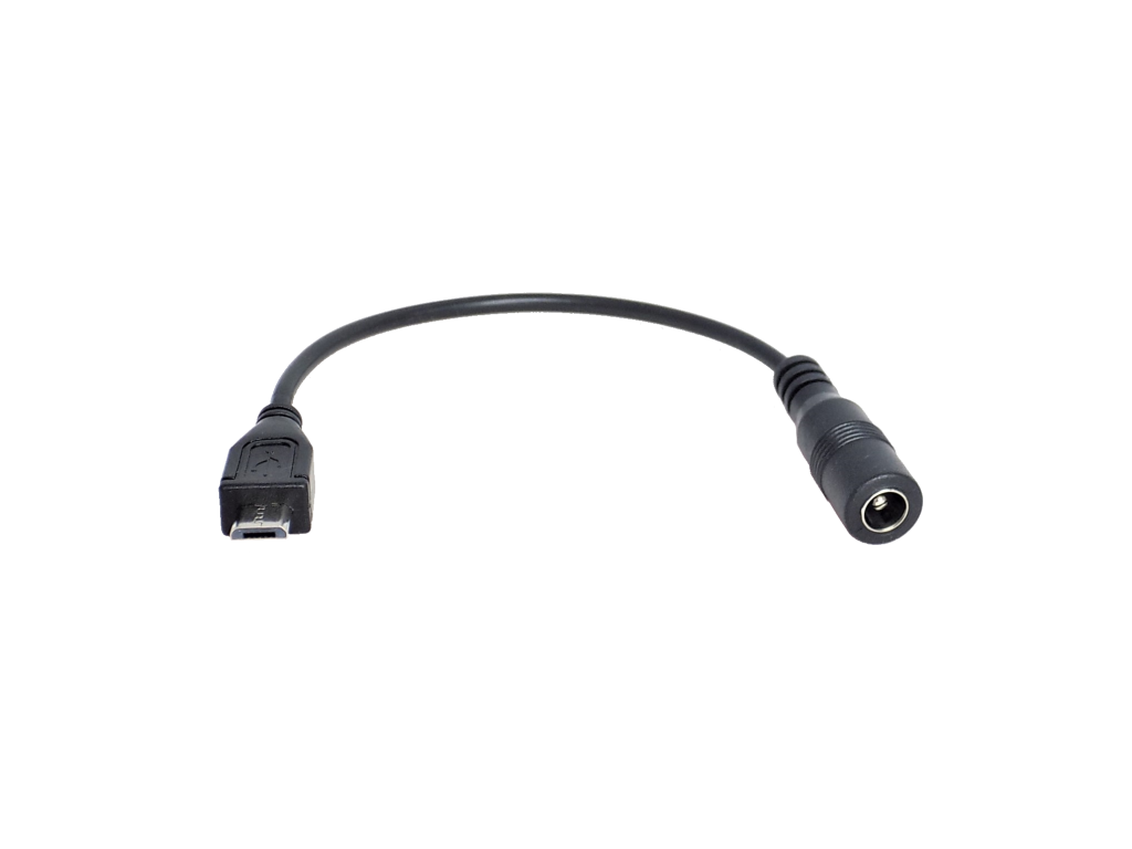
- a Birdcord PD 6V
- a Polarity Inverter Cable
- a USB-C PD power bank
- a USB-C cable to connect the power bank to the Birdcord
- your 6V Elektron model (Monomachine MKII, Machinedrum MKII, Octatrack MKI, or Sidstation)
Important additional info:
- Not all PD chargers are capable of outputting 12V. Check the specifications or get the recommended INIU PD charger
- These Elektron devices can be powered via Birdcord PD 12V: Digitakt I & II, Digitone I & II, Digitone Keys, Syntakt, Octatrack MKII, Analog Rytm MKI/MKII, Analog Four MKI/MKII, Analog Drive, Analog Heat MKI/MKII
- These Elektron devices can be powered via Birdcord Model:5V: Model:Samples, Model:Cycles
- These Elektron devices can be powered via Birdcord PD 6V + Polarity Inverter: Monomachine MKII, Machinedrum MKII, Octatrack MKI, Sidstation
- These Elektron devices can’t be powered via Birdcord (yet): Monomachine MKI, Machinedrum MKI, Overhub
If you have any questions, feel free to get in touch via email (dieter@songbirdfx.com) or Instagram.
(Post updated on April 21st, 2026)